TP·VAS auch auf Deutsch – technische Informationen und ProjektdokumentationZur deutschen Fassung

TP·VAS · Detailed reference documentation

Haus Düsse

Concrete protection retrofit for a secondary digester at the research and training centre of the Chamber of Agriculture of North Rhine-Westphalia..

Haus Düsse 2, 59505 Bad Sassendorf, Ostinghausen.

The Haus Düsse biogas plant is part of the agricultural research and training centre run by the Chamber of Agriculture of North Rhine-Westphalia. Since 2002, it has been used to generate energy and to test and demonstrate agricultural biogas technology.

In early summer 2026, a mechanically fixed thermoplastic concrete protection lining was installed in the existing secondary digester. The work comprised installing and welding the plastic sheets and integrating existing openings and pipe penetrations into the lining.

A particular feature of this project was the large number of existing fittings and connections that had undergone repeated modifications. The lining was tailored to these existing components.

1. Which concrete tank was lined?

The secondary digester at the Haus Düsse biogas plant was lined. The cast-in-situ concrete tank has a working volume of 1,000 m³.

Tank data

Tank function
Secondary digester
Construction
Cast-in-situ concrete
Internal diameter
16 m
Wall height
6 m
Working volume
1,000 m³
Lined area
262 m²

The plant also includes a primary digester with a working volume of 1,000 m³ and a digestate storage tank with a capacity of 2,100 m³. Neither of these tanks was included in the work described here.
2. What work was required on the existing tank?

The existing concrete was to be protected from the aggressive conditions inside the tank by a continuous plastic lining. The work covered the wall surfaces and the interfaces with existing fittings.

Initial condition

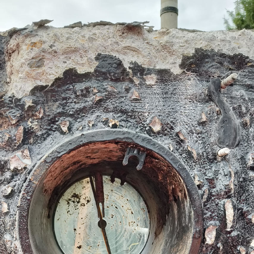
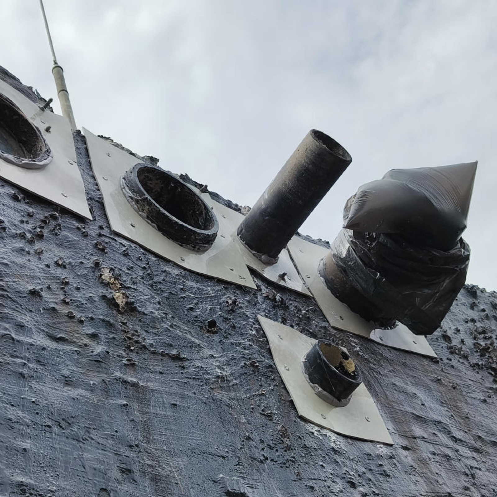
Damage to the concrete surface was visible around some existing connections. Photo 08 shows the condition around a circular opening before the new connection panel was installed. Some adjacent penetrations were closely spaced and differed in size.

Technical requirements

The protective barrier had to remain continuous around openings, pipe penetrations and fixings. This required connection pieces tailored to the existing components and welded transitions to the wall lining.

3. Which areas were actually lined?

The lined area totals 262 m². The work covered wall surfaces and the associated connections around openings, pipe penetrations and existing fittings.

Lined surfaces

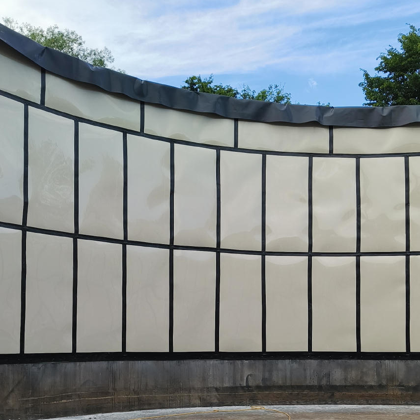
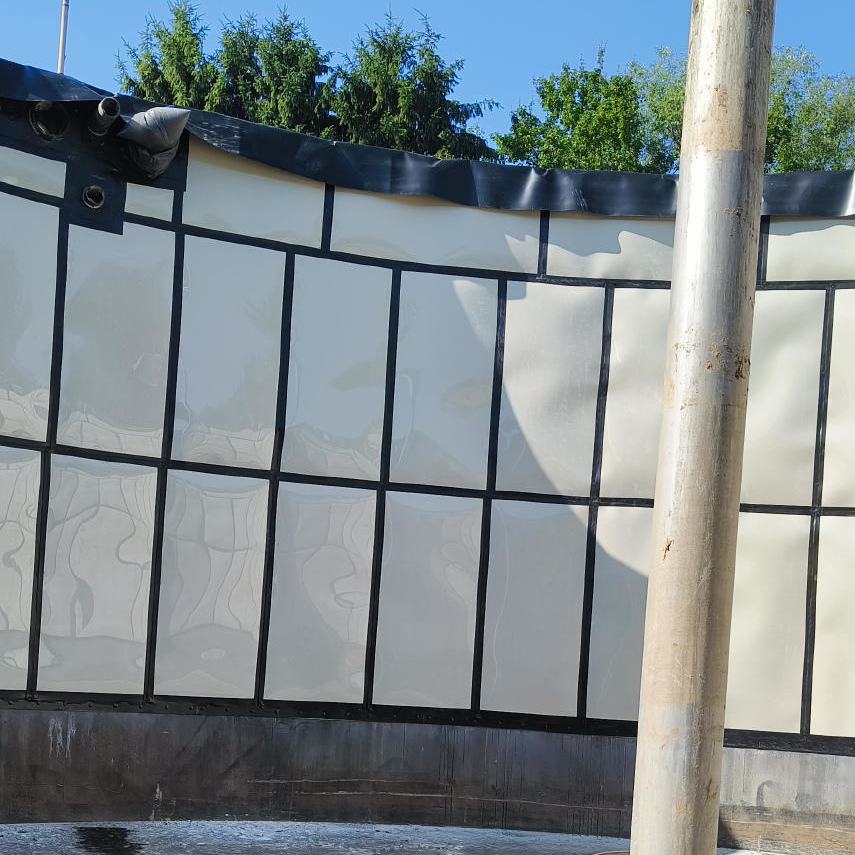
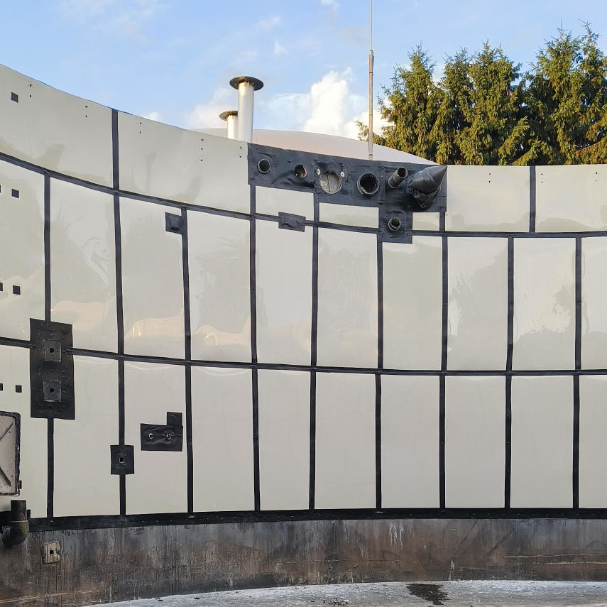
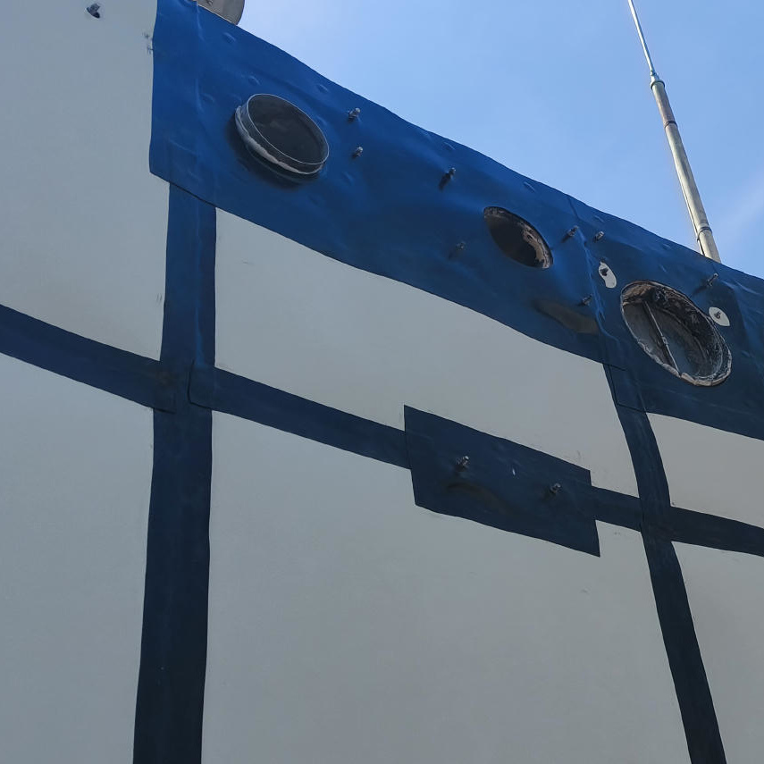
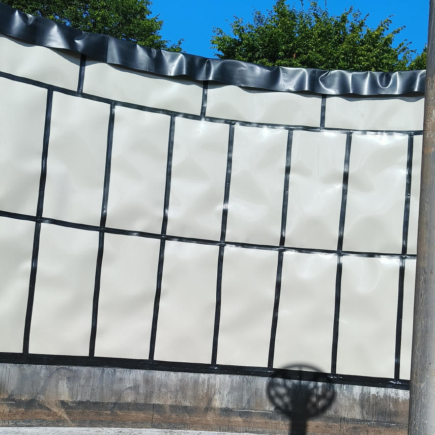
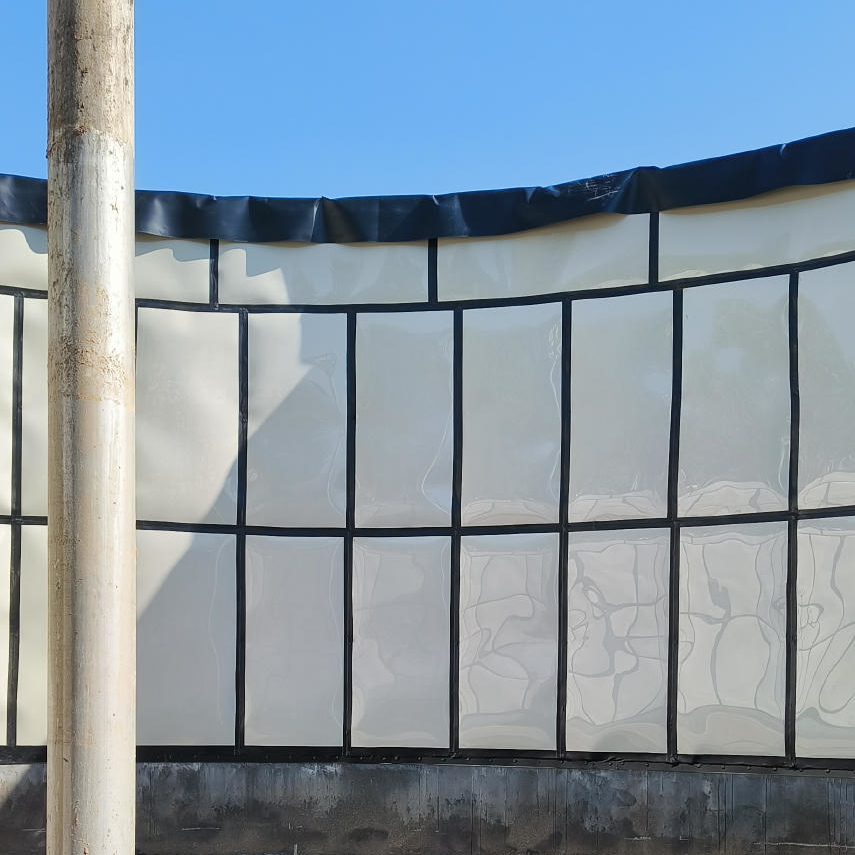
The sheets follow the curvature of the tank wall and are arranged in several rows. Photos 01 to 04 show the lining from four directions. A strip of exposed wall below the lining is visible in the photographs.

Connections and penetrations

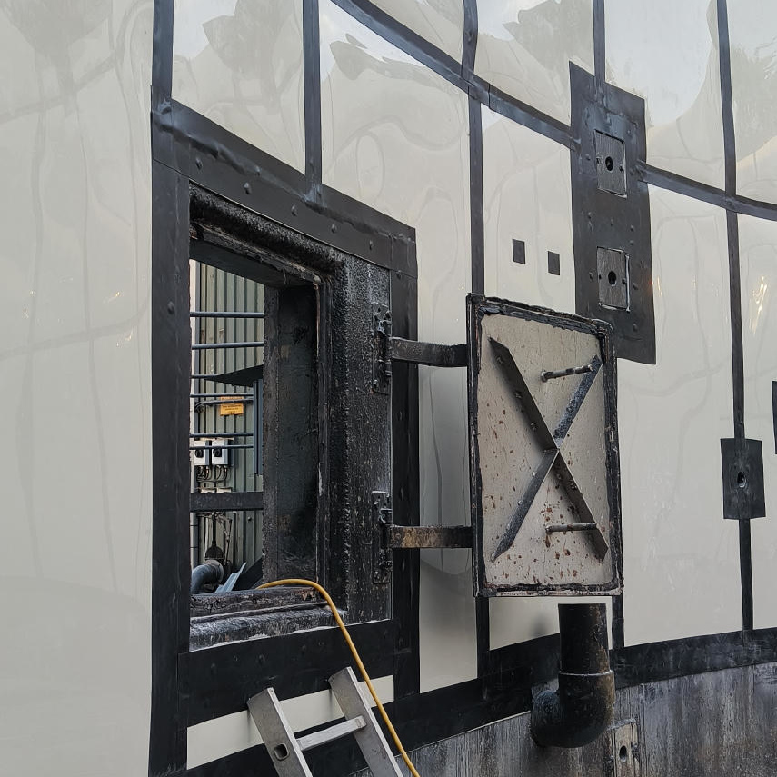
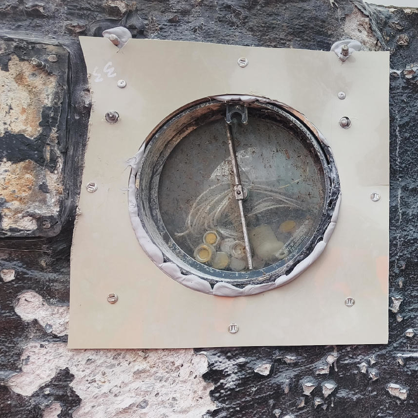
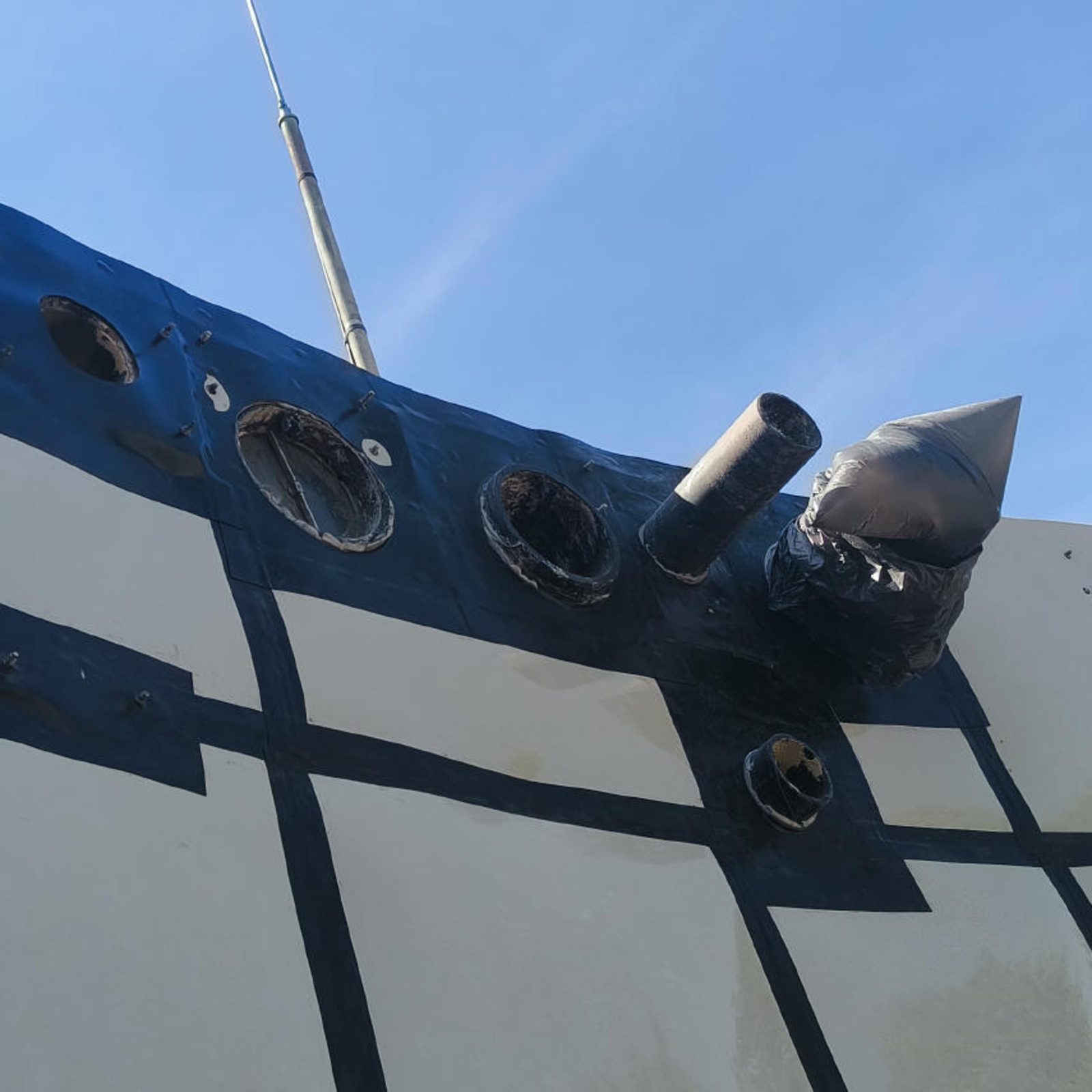
The existing manhole opening and several other openings and pipe penetrations were integrated into the wall lining, particularly in the upper part of the wall. Individual connection panels were cut to fit the different shapes and dimensions.

4. How was the work prepared and carried out?

The lining was installed using 2 mm thick PP-H sheets and 1.5 mm thick FPP cover strips. It was cut to size, mechanically fixed and welded on site.

Preparation

Cleaning with a conventional pressure washer was sufficient to prepare the surface. No further treatment by high-pressure water jetting or sandblasting was required.

Installation sequence

The PP-H sheets were cut to suit the tank geometry and mechanically anchored to the concrete. The joints and fixing areas were covered with FPP strips, which were welded to the sheets. At existing openings and pipe penetrations, the fitted connection pieces were welded to the wall lining.

5. Fixings and connections

Mechanical anchorage secures the lining to the structure. Welded covers protect the fixings from the environment inside the tank.

Mechanical fixing

The plastic sheets were anchored to the existing concrete. The fixing points are located in areas that were subsequently covered with welded plastic strips.

Covering the metal components

The metal fixings for the lining are covered by thermoplastic strips. These were welded to the lining along their edges, isolating the fixings beneath them from the tank environment.

Special connection details

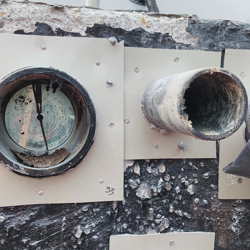
The manhole opening and existing pipe penetrations were integrated into the lining using fitted connection pieces. At the closely spaced openings in the upper wall, individual connection panels were installed first and then joined to the wall lining using welded cover strips.

6. Welded joints

The sheets, cover strips and connection pieces were welded together on site to form a continuous protective barrier.

Welding process used

[Insert documented procedures and materials.]

Inspection

Hot-gas overlap welding produces durable, leak-tight joints between the lining sheets, the covers over the fixings and the custom-fitted connection pieces.

DVS Technical Code 2207-3 (12/2019)

7. Photo documentation

Photos 01 to 04 show the lined wall surfaces from four directions. The arrangement of the sheets and the welded cover strips can be seen.

Photos 05 to 07 show the connection to the manhole opening and other openings and pipe penetrations in the upper part of the wall

Photos 08 to 12 show individual stages of the work: damaged concrete around an existing opening, the installation of fitted connection panels and their subsequent integration into the wall lining.

Wall lining, north view. The dark plastic strips cover the joints and fixing areas.
Photo 01 · Wall lining, north view. The dark plastic strips cover the joints and fixing areas.
Wall lining, east view.
Photo 02 · Wall lining, east view.
Wall lining, south view.
Photo 03 · Wall lining, south view.
Wall lining, west view.
Photo 04 · Wall lining, west view.
Connection between the wall lining and the existing manhole opening.
Photo 05 · Connection between the wall lining and the existing manhole opening.
Overview of the fitted connections and penetrations in one section of the wall.
Photo 06 · Overview of the fitted connections and penetrations in one section of the wall.
Connection area around several adjacent openings at the top of the tank wall.
Photo 07 · Connection area around several adjacent openings at the top of the tank wall.
Before the connection area was lined: damaged concrete around an existing circular opening.
Photo 08 · Before the connection area was lined: damaged concrete around an existing circular opening.
A plastic connection panel cut to fit around the existing opening. The fixings are still exposed at this stage.
Photo 09 · A plastic connection panel cut to fit around the existing opening. The fixings are still exposed at this stage.
Adjacent openings with individually fitted connection panels during installation.
Photo 10 · Adjacent openings with individually fitted connection panels during installation.
Several connection panels during installation; the adjoining wall surface has not yet received the new lining.
Photo 11 · Several connection panels during installation; the adjoining wall surface has not yet received the new lining.
Connection area with welded cover strips after integration into the wall lining.
Photo 12 · Connection area with welded cover strips after integration into the wall lining.

8. What does this case study demonstrate technically?

The project demonstrates how an existing concrete tank can be retrofitted with mechanically fixed and welded plastic sheets.

The installation was adapted to the existing tank geometry, the manhole opening and the different arrangements of penetrations. The detailed photographs show how the individual connection panels and the wall lining were joined to form a continuous protective barrier.

The project illustrates how an existing tank can be fitted with a separate protective lining without rebuilding the concrete structure.

9. What determines long-term protection?

The chemical resistance of the plastic sheets alone is not sufficient. The protective barrier must also remain continuous at welds, fixing points and connections.

Leaks at connections can allow aggressive liquids to penetrate behind the lining and attack the concrete and fixings. Covering the fixings and sealing the penetrations are therefore just as important as lining the wall surfaces.

If additional connections are installed or existing components are modified at a later date, the affected areas must be sealed and integrated back into the lining.